×
The platform for the Entire Casting Industry
Partner
Foundry Corporate News
Saving energy when melting metals in induction furnaces through practical measures and by analyzing digital melting process data
Reading time: min
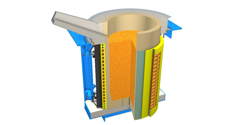
If the induction furnace is designed as a coreless furnace (s. figure 1), a ceramic crucible is located inside a cylindrical copper coil. The material charged into this crucible is exposed to an electromagnetic field generated by the current flowing through the copper coil. This field induces eddy currents in the metal. The ohmic losses of these eddy currents heat the metal and ultimately liquefy it.
Such coreless induction furnaces achieve efficiencies of over 80 % for ferrous materials and over 70 % for highly conductive materials such as copper or aluminum, provided that the coil is made from highly conductive copper and yokes made of transformer sheet laminations are installed to provide a return path for the magnetic field.
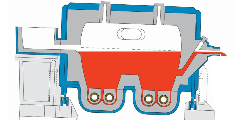
Alternatively, an induction furnace can also be built based on the principle of the channel-type furnace (s. figure 2). In this case, a so-called channel inductor (or several of them) (s. figure 3) is flanged to a furnace uppercase. The liquid melt is heated according to the principle of a short-circuited transformer. A copper coil forms the primary winding, and a channel of liquid metal forms the short-circuited secondary winding. The short-circuit current of the transformer then flows through this channel, and its ohmic losses in turn heat up the metal. The efficiencies achieved with this electrical principle are even 10 to 15 percent points higher compared to the coreless furnace principle. However, it has the disadvantage that the furnace may never be completely emptied, which limits its versatility with regard to alloys and operation.

One major advantage of the coreless furnace design is that significantly higher outputs can be achieved. As a result, coreless furnaces for iron and steel with more than 20 MW power rating and melting rates in excess of 40 t/h are successfully in use.
Even if induction furnaces can be operated carbon-free when powered by electricity from renewable sources, the foundries using them still strive to minimize their electricity consumption. This is done with sustainable resource conservation in mind, and also with a view to improving the profitability of foundries and factories manufacturing semi-finished products, especially in the face of rising energy costs. Liquefying ferrous or aluminum materials requires approx. 500-560 kWh/t, which means that energy costs are often a decisive factor in the manufacture of castings and semi-finished products.
So how can a foundry save energy during the melting process? There are three main influencing factors:
- Dimensioning of the system and the terms of the electricity supply contract
- Operating regime of the melting furnaces in practice
- Analysis of digital melting process data
Rating and dimensioning of the system and considering the terms of electricity supply contracts
Today's electricity supply contracts usually apply demand charges, unit charges and reactive demand charges. The costs associated with the demand charge can be reduced by ensuring that the system draws energy from the grid as consistently as possible. Utilities charge hefty mark-ups for peak energy demands, for which after all they have to make provisions on the power generation side and grid side. It therefore makes sense to rate and dimension a melting furnace in such a way that the planned liquid metal requirement is covered, but the temporary maximum requirement is achieved where possible through additional production times. Maximum-power monitoring systems, which ensure that previously-defined loads are throttled when the power limit is reached, are also helpful in this regard. Induction furnace systems with pulse width modulated IGBT inverters offer an advantage for this mode of operation because they have a constant power factor cos phi even in the partial load range, while maintaining very good electrical efficiency of the parallel resonant circuit converter. Series resonant circuit converters too achieve a constant mains power factor. With these, however, the high uncompensated furnace current must be fed through the entire inverter, leading to additional losses and increasing the strain on components.
The unit charge in the electricity supply contract determines the price per kWh consumed, which must be paid by the foundry. For example, if this is 20 cents per kWh and the furnace consumes 550 kWh per tonne of liquid metal, the unit charge per ton of cast or semi-finished products would be € 110.
In some grids, the unit charge may also vary depending on the time of day or day of the week. In such cases, it may make sense to install a holding furnace or a furnace system with two or three crucibles to store liquid metal that was produced during a low-tariff period.
Whether additional costs have to be paid for the reactive power used depends on the one hand on the consumption of reactive power permitted by the energy supplier and, on the other hand, on whether the induction furnace has a constant cos phi of 0.99, for example, at the converter input also in the partial load range.
If the unit charge does not have a low tariff and the liquid metal demand is relatively constant, it is better to avoid installing additional holding furnaces where possible. For instance, a 60-tonne holding furnace for iron, designed as a channel-type induction furnace, has an annual energy demand of approx. 2 million kWh. Based on the example of 20 cents per kWh, this equates to energy costs of € 400,000 per annum.
Operating regime of the melting furnaces in practice
Just like smart driving habits will maximize a car’s fuel economy, a significant proportion of the energy needed to operate an induction melting furnace can be saved simply by adopting smart operating strategies. This starts with the chosen method and further processing of the charge material.
Savings measures can therefore be divided into two categories: Optimization of the type and quality of the charge material and optimization of the process flow.
Often no particular attention is paid to surface contamination because there is no visual difference. The material seems to melt just as well as clean metal. After the melting process, the non-metallic impurities are removed in the form of slag.
The fact is, however, that these impurities result in a poorer overall coupling of the scrap to the induction field. In the case of oxides, these do not even couple at all, which leads to poorer overall power utilization.
In practice, such insights are usually only gained by evaluating the production data. If irregularities are detected in the process or in the product quality, action needs to be taken and the process must be systematically examined.
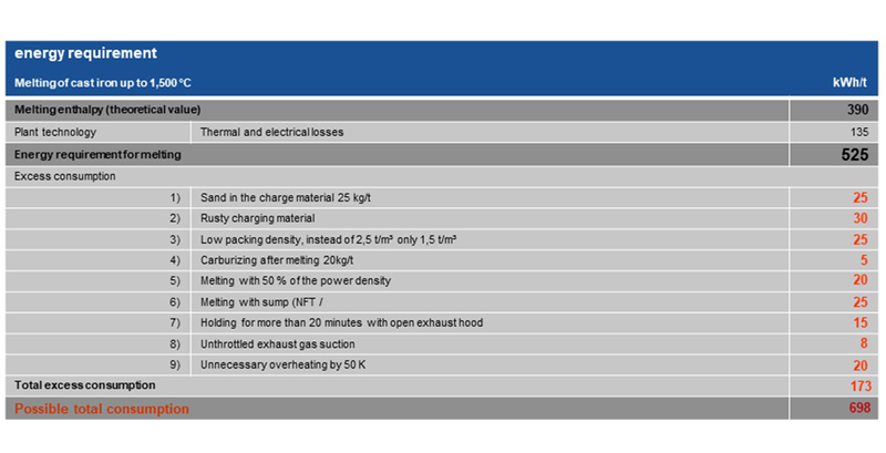
Below are some examples of process situations and corresponding orientation values for potential energy savings when melting down a batch, as calculated in various iron foundries.
1) Sand in the charge material
After the molds have been shaken off, varying amounts of molding sand still adhere to the recycled material. If these are not adequately removed by blasting, sand will get into the melt. The formation of slag from the sand also takes energy. With a realistic quantity of 25 kg of sand per tonne of iron, this results in an increased requirement of 25 kWh/t.
2) Rusty charge material
Depending on how the scrap used is stored, rust (iron oxides) can form and be introduced into the crucible. The poor coupling leads to a lower power input. The iron oxide must be heated to the melting temperature in an energy-intensive process. For the furnace stated in the table (s. figure 4), this means an additional consumption of 30 kWh/t.
3) Low packing density
The packing density of the charge material also affects energy consumption: The higher the packing density, the lower the energy consumption.
Tests in practical operation showed a lengthening of the melting process by approx. 8 % and an increase in energy consumption by approx. 25 kWh/t with a reduction in packing density from 2.0 t/m3 to 1.3 t/m3.
4) Carburizing after melting
If the carburizing agent is not added at the beginning of the melting process along with the metallic feedstock, but only introduced into the liquid bath after melting, this results in a significantly higher energy consumption. Based on practical experience, it has been ascertained that an additional 1 to 2 kWh/kg is required if the carburizing agent is added later. With a realistic value of 1 % carburizing agent per batch, a higher energy requirement of up to 5 to 10 kWh/t iron can therefore be expected.
5) Melting with reduced power density
Based on theoretical considerations, the most energy-efficient way to operate the furnace is with the maximum
available electrical power and thus a high power density. Systematic tests carried out clearly confirm this. Batch times are shortened, thermal losses are reduced, and consequently, electricity consumption is lower. For example, if the furnace in the table operated at only 50 % of the maximum power, this results in an additional electricity consumption of 20 kWh/t.
6) Melting with a sump
If medium frequency technology is used, a sump can be dispensed with
and small-sized charge material can be melted. Due to the better
electromagnetic coupling of the solid feedstock (this only applies to cast iron materials), 5 % less energy is required in batch-only operation,
as a significantly higher coil efficiency is achieved up to the Curie point.
7) Holding with the lid open
If a furnace is operated with the lid open for longer than necessary, a considerable amount of heat escapes into the shop. This energy has to be replaced. The small thermal loss of originally only around 275 kW (for a 15-tonne furnace) then rises to around 600 kW. If the lid is left open for a period of 20 minutes, this results in an increased energy requirement of 15 kWh/t in total.
8) Unthrottled extraction
The extraction volume of the flue gas cleaning system should be adapted to the process steps of the furnace. Thus, if no flue gases are to be extracted or only small amounts are produced, the extraction volume can be throttled.
If the filter system is always operated at full capacity, energy is unnecessarily “sucked” out of the furnace. In unfavorable cases, this can increase energy consumption by around 2 %. In the example in the table below, this is estimated at 8 kWh/t.
9) Unnecessary superheating
If the superheating of the iron is not checked in good time during the final melting phase in manual mode, the desired or sufficient casting temperature may be exceeded unnecessarily. By avoiding an excessive temperature increase of 50 K, for example, approx. 20 kWh/t can be saved.
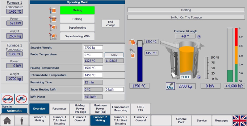
If a digital furnace control system is used, the final temperature can be maintained with an accuracy of up to 5 K in automatic mode. This helps prevent unnecessary superheating.
To illustrate this, the table shows energy values for a furnace with a capacity of 8,000 kg of cast iron, operated at a maximum power of 7,000 kW.
Of course, these individual cases never all arise at the same time. However, the total sum shows that the required energy demand could even be exceeded by more than 35 % in the worst case.
Based on the initially assumed electricity costs of 20 cents per kWh,
this increases the cost of producing one tonne by about € 30. For an annual production of 50,000 metric tons, this results in avoidable additional costs of approx. € 1,500,000.
Once aware of the causes, it is very easy to avoid wasting energy by establishing routine actions and optimizing the system with the help of quality monitoring and process control.
The same software that is used to operate the furnace can be extended to include such helpful modules as recipe management or process step confirmation. This allows individual goals to be pursued depending on the foundry process and melting task.
Analysis of digital melting process data
Modern induction furnaces have a PLC controller and a process computer that stores all important melting process data and assigns it to a specific batch. Complete batch documentation contains the following information (s. figure 5):
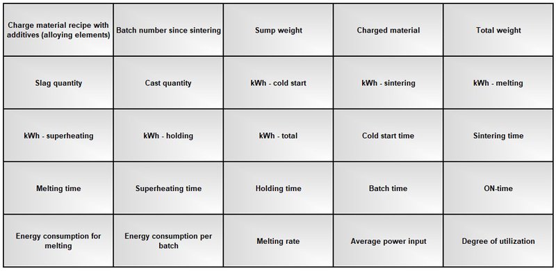

Optionally, data such as the length of time the lid is open, times of high and low extraction flowrates, optimal or delayed charge material input and optimal or delayed material discharge can also be recorded.
A batch diagram provides an overview of charge material input, temperature and power input plotted against the batch time. For the purpose of comparison, an “ideal batch” can optionally be stored, which the operator then strives to achieve by charging as efficiently as possible. For this type of operation, which strives to continuously improve throughput and energy consumption, it is advisable to install a separate computer with its own clear dashboard in order to separate the operational optimization process from visualization of the furnace system sensors.
This gives furnace operators clear real-time information on how efficiently they have operated the furnace in terms of energy consumption. This also helps to motivate operators because they can directly see the economic impact of their working method or of different scrap qualities.
The analysis of this melting process data can also be supported by artificial intelligence in order to find patterns of “good or bad” batch results depending on the numerous parameters, and to develop recommendations for optimizing charge materials and furnace operation.
Unlocking Efficiency Through Data-Driven Practices
In the realm of foundries, the efficient operation of melting furnaces relies heavily on streamlining through data analysis. Successful implementation of operating procedures (SOPs) plays a pivotal role in optimizing energy consumption.
Achieving Ideal Melting Processes:
An ideal melting process is characterized by a continuously rising cumulative energy consumption curve. Prolonged ‘flat periods’ on this curve indicate suboptimal melting conditions. However, due to a lack of data visibility, furnaces often operate based on individual operator experience and subjective best practices. The challenge intensifies as operators manage multiple furnaces across vast shop floors, making it difficult to obtain timely insights.
Operator Nudging Dashboards
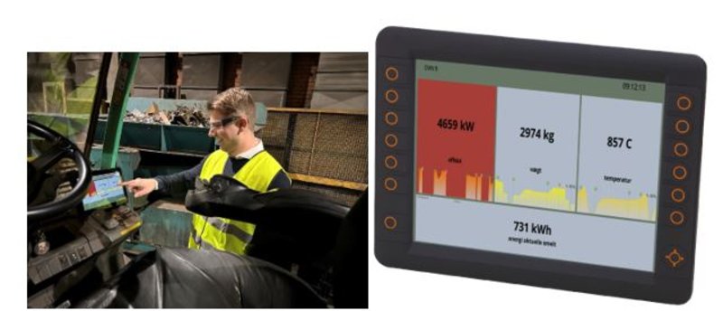
Take, for example, a major foundry in Northern Europe consuming 100 GWh annually. In pursuit of optimal conditions, surveys indicated that melting one metric ton of scrap metal into molten iron should ideally require about 560 kWh. However, the actual average until recently was 640 kWh per t melt. To address this the foundry collaborated with a company from Denmark who offers IoT based energy optimization services specific for foundries.
Experts analyzed the data from multiple melting batches to identify the ideal operating procedures and organized the information into real-time operator dashboards. Mounted in the operator's work area (s. figure 8 a and b), these dashboards display temperature, energy consumption, and furnace weight. They also provide a clear visual guide for the ideal timing to fill and empty the furnaces. This initiative significantly reduced the average energy consumption to 570 kWh/t, translating to an annual saving of close to € 1 million for the melting process alone.
Achieving Energy Balance
Building on these experiences the iron foundry integrated existing furnace data with MES and ERP systems to align production with low-energy pricing periods. While this may seem like a cost-cutting strategy, it also addresses the broader goal of supporting the grid's stability driven by increased use of renewable energy sources.
By strategically adapting the power level of electricity-powered equipment for short intervals (5-15 minutes), foundries can obtain large refunds from Transmission System Operators (TSOs) by entering Energy Balancing without significant impact on production. For foundries using induction furnaces it is a great opportunity leveraging readily available data from furnaces, MES, and ERP systems to navigate towards sustainability, efficiency and lowered carbon footprint.
References:
- Trauzeddel, D. (2018) Spezielle Anwendungen der induktiven Schmelz- und Gießtechnik. Einsatzgebiete | Anlagenbau | Prozesstechnik. Vulkan Verlag.
- Dötsch, E. (2019) Induktives Schmelzen und Warmhalten. Grundlagen | Anlagenaufbau | Verfahrenstechnik. Vulkan Verlag.
- Donsbach, F.; Schmitz, W.; Trauzeddel D. (2018) OTTO JUNKER Handbuch: Sicheres und energiesparendes Schmelzen im MF-Tiegelofen. Selbstverlag.
- Donsbach, F.; Renftle, G.; Niklaus, S. (2021) Das Einschmelzen von Schrotten geringer Packungsdichte im Mittelfrequenz- Induktion-Tiegelofen. Technical article.
- OTTO JUNKER Academy
- Photos: OTTO JUNKER Archive
- Photos: INDUGA Archive
- Init Group
Authors:
Frank Donsbach – OTTO JUNKER GmbH, D-52152 Simmerath-Lammersdorf
Matias Mohedano Rodriguez – OTTO JUNKER GmbH, D-52152 Simmerath-Lammersdorf
Ulrich Nordt – OTTO JUNKER GmbH, D-52152 Simmerath-Lammersdorf
Peter Koldig Hansen, Init Inuatek A/S, DK-1432 Kopenhagen
Company Info
OTTO JUNKER GmbH
Jägerhausstr. 22
52152 Simmerath
Germany
Telephone: +49 2473 601-0
Email
info(at)otto-junker.com
Web:
www.otto-junker.com
Related articles
-
Leading the Charge: HYDROTEC's Commitment to Climate Protection
read more ...
-

Power-to-Heat technology for sustainable industrial processes
read more ...
-

Make Efficiency simple - With OTTO JUNKER and OCP+
read more ...
-

OTTO JUNKER - Leading the way for 100 years
read more ...
-

Environmentally friendly heating without compromise: EcoJet and JuDy by OTTO JUNKER
read more ...
-

OTTO JUNKER strengthens its position as a trendsetter in the field of environmentally friendly melting and heat treatment plants
read more ...
[106]